 Strangelight Audio
Connections and sockets
A cable carries one kind of signal from an output socket to an input socket. Outputs sit on the right of a node and inputs on the left. Most surprises come from connecting two sockets of the same kind that mean different things, so this page starts with the canvas and ends with the reference tables.
Make a connection
- Socket to socket: drag from an output to an input and release over the input socket.
- Socket to empty canvas: drag from a socket and release over empty canvas. A menu lists only the nodes that can connect there. Choose one to add it already connected.
- Into an existing cable: zoom in until a + appears at the middle of a cable, then click it. Choose a node to insert between the two ends.
- One output, many inputs: an output can feed any number of inputs. Drag from it again to add another cable.
To remove a cable, click it and press Option+Shift+Delete (macOS) or Alt+Shift+Delete, or drag across it with the Cut tool (B). See Editing and navigation.
Read what a cable carries
Turn on Help at the bottom left of the editor, then point at a socket or cable. Its details appear above the Help button. For a cable it shows the kind, the range and both ends, for example Audio connection: Audio · Normalized · −1 to 1, Oscillator · Signal → VCA · Signal.
Three properties decide what a connection does:
- Kind is what flows: audio, control, gate, trigger, MIDI or a structured type such as Clock.
- Unit is what a number means: Hz, milliseconds, a MIDI note number or a 0–1 level.
- Range is the values the socket expects.
Look at Lesson 2 of Build a synth. ADSR Envelope and Filter Cutoff are both control sockets, but the envelope moves between 0 and 1 while Cutoff expects 20 Hz to 20 kHz. Map Range turns one range into the other, so the envelope sweeps a cutoff range you choose. When a connection works but sounds wrong, compare the two sockets' units and ranges first.
Parameter inputs
Many controls have a socket at the left end of their row. That socket is a parameter input: connect a cable to it and the cable sets the parameter.
- While a cable drives a parameter, its slider no longer responds to dragging. Remove the cable to set the value by hand again.
- A parameter has one driver at a time: its own control, one cable or one Macro. A parameter assigned to a Macro refuses a cable until you remove it from the Macro.
Refused connections
Throughline refuses a connection that cannot work and tells you why. A refused drag shows Invalid connection with the reason. Common reasons:
- Incompatible socket: the two kinds cannot connect, for example an audio output into a MIDI input.
- Choose an input socket as the target: both ends are outputs. Drag from an output to an input.
- Both sockets belong to the same node.
- Map Range is locked to …, but this target expects …: a Map Range that already drives one kind of target cannot drive a different one.
- Polyphony Zones don't take audio input: a Zone accepts notes, not audio. See Polyphony.
- … is controlled by a Macro: remove the Macro binding first.
For more fixes, see Cannot connect these sockets.
Warned connections
Some connections work but may not mean what you expect. Throughline accepts them and marks the cable with a small badge. Point at the badge to read the warning.
A gate driving a frequency input is an example: it works, because a gate is 0 or 1, but it is rarely musical. MIDI connected straight into a number input also works with a warning. Use MIDI Decode when you want pitch, gate and velocity as separate, clear signals.
Group boundaries
Inside a Group, the Group Input and Group Output nodes each have an add socket. Drag a cable to an add socket to expose that signal on the Group's node in the parent canvas. See Frames, Groups and Zones.
Socket shapes and colours
Each socket's shape and colour show its kind. The label always names the kind too, so you never have to rely on shape or colour alone.
| Socket | Kind | Shape | Carries |
|---|---|---|---|
 |
audio |
Filled circle | Full-band audio signal |
 |
control |
Filled circle | Normalized control/CV signal for parameter modulation |
 |
string |
Tall rectangle | String-backed enum value |
 |
gate |
Filled circle | Gate signal (0/1) |
 |
clock |
Diamond | Musical phase clock signal |
 |
timeSignature |
Diamond | Musical meter carried as numerator and denominator |
 |
trigger |
Filled circle | Trigger pulse |
 |
midi |
Diamond | MIDI note/CC data |
 |
scale |
Diamond | Musical key and scale selection |
 |
number |
Filled circle | Control/parameter value |
 |
event |
Filled circle | Discrete pulse/clock/gate |
 |
sequence |
Diamond | Timed step sequence with values and durations |
 |
bool |
Hollow circle | Boolean/toggle |
 |
bufferAudio |
Filled circle | Audio buffer |
 |
bufferFFT |
Filled circle | FFT buffer |
 |
unknown |
Hollow circle | Unconnected wildcard input; adopts the connected signal type |
Signal type reference
Every signal kind that can flow between sockets, with its normalized range and unit hint. This table comes from the same vocabulary as the editor's socket details.
| Kind | Name | Meaning | Range | Unit |
|---|---|---|---|---|
audio |
Audio | Full-band audio signal | -1 to 1 | float |
control |
Control | Normalized control/CV signal for parameter modulation | 0 to 1 normalized | cv |
string |
String | String-backed enum value | catalog-defined | string |
gate |
Gate | Gate signal (0/1) | 0 or 1 | gate |
clock |
Clock | Musical phase clock signal | beats from clock origin | beats |
timeSignature |
Time Signature | Musical meter carried as numerator and denominator | positive numerator / power-of-two denominator | meter |
trigger |
Trigger | Trigger pulse | 0 or 1 | trigger |
midi |
MIDI | MIDI note/CC data | 0-127 | note numbers / CC |
scale |
Scale | Musical key and scale selection | catalog-defined | scale |
number |
Number | Control/parameter value | 0-1 (unipolar) | number |
event |
Event | Discrete pulse/clock/gate | 0 or 1 | gate/trigger |
sequence |
Sequence | Timed step sequence with values and durations | varies | steps |
bool |
Boolean | Boolean/toggle | true/false | — |
bufferAudio |
Buffer Audio | Audio buffer | n samples | buffer |
bufferFFT |
Buffer FFT | FFT buffer | spectrum | buffer |
unknown |
Unknown | Unconnected wildcard input; adopts the connected signal type | varies | — |
Units
Control signals share one kind but carry different meanings depending on their unit:
| Unit | Name | Meaning |
|---|---|---|
Hz |
Hertz | Frequency in cycles per second |
kHz |
Kilohertz | Frequency in thousands of cycles per second |
cents |
Cents | Pitch offset — 100 cents per semitone |
semitones |
Semitones | Pitch offset in semitone steps |
octaves |
Octaves | Pitch offset in octaves |
midiNote |
MIDI Note | MIDI note number (0–127, 69 = A4) |
midiVelocity |
MIDI Velocity | MIDI note velocity (0–127) |
midiChannel |
MIDI Channel | MIDI channel number (1–16) |
midiCC |
MIDI CC | MIDI continuous-controller value (0–127) |
v/oct |
Volts per Octave | Pitch CV — one unit per octave |
bpm |
BPM | Tempo in beats per minute |
beats |
Beats | Musical position or offset measured in quarter-note beats |
ms |
Milliseconds | Time in thousandths of a second |
s |
Seconds | Time in seconds |
samples |
Samples | Time in audio samples |
dB |
Decibels | Level in decibels |
normalized |
Normalized | Unitless value in a shared normalized range |
gain01 |
Gain (0–1) | Linear level from 0 (silent) to 1 (unity) |
phase01 |
Phase (0–1) | Normalized phase across one cycle |
pan |
Pan | Stereo position from left (−1) to right (+1) |
degrees |
Degrees | Angle in degrees |
Q |
Q | Filter resonance / quality factor |
ratio |
Ratio | Dimensionless ratio between two quantities |
percent |
Percent | Proportion expressed from 0 to 100 |
mix01 |
Mix (0–1) | Dry/wet blend from 0 (dry) to 1 (wet) |
bits |
Bits | Resolution in bits |
grainsPerSec |
Grains per Second | Granular density in grains per second |
count |
Count | Integer count of discrete items |
division |
Division | Musical time division (e.g. 1/4, 1/8) |
Conversion reference
How Throughline treats mismatched sockets
Each input declares how it accepts other kinds. A connection is one of:
- Direct: the kinds already match.
- Implicit: Throughline converts the signal on the cable. MIDI into a control, gate or trigger input works this way.
- Risky: allowed with a warning badge, because meaning may be lost.
- Forbidden: refused.
Some pitch and control conversions happen on the cable, so a direct connection can be enough. Add a conversion node when you want the conversion visible, reusable or shared by several destinations:
| To do this | Use |
|---|---|
| Turn MIDI into pitch, gate, velocity, bend | MIDI Decode |
| Read a MIDI controller as a 0–1 value | CC Extractor |
| Switch between Note, Hz and V/Oct pitch | Convert |
| Turn pitch and gate back into MIDI | MIDI Encode |
| Move a signal into another range | Map Range, Clamp |
| Turn a continuous signal into a gate or event | Compare |
| Scale an audio level | Gain, VCA |
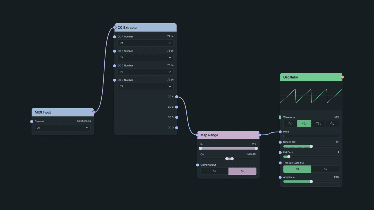
A MIDI controller made audible: CC Extractor reads the controller as 0–1, and Map Range turns it into a pitch range.
Normalized ranges
A normalized range is a shared expected range: audio usually runs from −1 to +1, and modulation from 0 to 1 or −1 to +1. It is not a safety limit. A normalized signal still clips if you amplify it, and Mix adds signals without limiting the result.
Named modes
Some settings take named values rather than numbers, such as Oscillator Waveform and Filter Filter Type. Choose them on the node. Numbers and control signals do not convert into named modes.
Gates and triggers
A gate is a held on/off state, such as a held key. A trigger is a one-moment event, such as the Trigger output of MIDI Decode or the Reset input of a Clock. Use a gate for anything that lasts and a trigger for anything that happens once.